| Go back to our Home Page |
![]()
After over 30 years supplying the services denoted below, HW Associates Ltd/HW Technical Services Ltd has been incorporated
into TCS CAD & BIM Solutions Ltd in order to provide a spares service for existing Head Wrightson equipment.
|
|
||
|
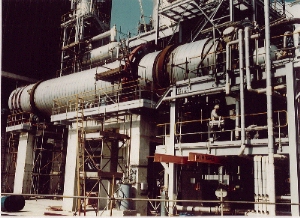
Steam tube dryers have been built for a variety of customers over a period of years. Among the most sophisticated have been the TA and PTA dryers installed at ICI Petrochemicals Division's Terephthalic Acids Plant at Wilton, Cleveland. A typical outline specification for one dryer is given below.
The shell is fabricated from stainless steel plate in one section, with longitudinal and circumferential butt welded joints. The shell beneath the girth gear ring and tyres is increased in thickness with tapered edges to match the nominal shell thickness. Steel pads are welded to the thickened plates which are machined for the attachment of shims and tyre support saddles. A steel flange is welded to the thickened plate at girth gear ring location and is machined to suit the gear ring fixing.
The product is introduced into the dryer through a screw conveyor and stainless steel feed hood, fitted with HW Associates patented seal arrangement, and is discharged through peripheral holes in the shell into a stainless steel discharge hood and chute, which is likewise fitted with our patented seal arrangement. The tyres are cast or forged steel machined solid section in one piece and are located on support and thrust rollers which in turn are carried on heavy steel section bedplates fitted with heavy steel adjusting screws for both support and thrust rollers. Each support and thrust roller is fitted with a pair of spherical roller bearings, together with seals to prevent the ingress of dirt, mounted on a fixed turned steel spindle. Lubrication of all
rollers is by grouped grease nipples piped and mounted at a convenient
point on the bedplate. The drive is transmitted from the motor through a vee-rope drive to the high speed shaft of a totally enclosed helical gear unit. The low speed shaft of the gear unit is coupled through a resilient grid spring coupling to the pinion shaft, which carried the pinion, meshing with the girth gear ring. The girth gear is manufactured from cast steel in halves with machined joints secured together with turned and fitted bolts. Automatic lubrication
is provided for the girth gear/pinion and the tyre/roller faces. The
system for the girth gear is a fully automated air/oil spray system
whilst that for the tyres is a motor driven oil drip feed system. E-mail us regarding dryers : dryers@headwrightson.co.uk |
||
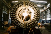
 Stainless steel heating
tubes are arranged equally around the circumference of the shell, these
tubes being welded into a stainless steel tubesheet at the product
discharge end, and fixed by means of a stainless steel seal mounting
plate at the product inlet end. Longitudinal flights can be welded to
the inside of the shell on the same radial centre line as the outer row
of steam tubes. The mounting plate has a tube gland sealing arrangement
which allows for the differential expansion of the drum and tubes. The
tubes are supported along their length by stainless steel hangers welded
to the shell. The discharge end is fitted with a rotary steam union
through which steam enters and condensate is removed and the tubes
project through the gland housings at the feed end and are fitted with
bleed plugs to bleed the air from the system and ensure the presence of
steam. Steam condenses inside the tubes and the condensate is returned
to the steam header by virtue of the slope of the dryer, from where it
is removed through the steam union by means of a syphon tube.
Stainless steel heating
tubes are arranged equally around the circumference of the shell, these
tubes being welded into a stainless steel tubesheet at the product
discharge end, and fixed by means of a stainless steel seal mounting
plate at the product inlet end. Longitudinal flights can be welded to
the inside of the shell on the same radial centre line as the outer row
of steam tubes. The mounting plate has a tube gland sealing arrangement
which allows for the differential expansion of the drum and tubes. The
tubes are supported along their length by stainless steel hangers welded
to the shell. The discharge end is fitted with a rotary steam union
through which steam enters and condensate is removed and the tubes
project through the gland housings at the feed end and are fitted with
bleed plugs to bleed the air from the system and ensure the presence of
steam. Steam condenses inside the tubes and the condensate is returned
to the steam header by virtue of the slope of the dryer, from where it
is removed through the steam union by means of a syphon tube.